Introduction to general design of domestic service water supply systems - with pressurized or gravity tanks
The purpose with a domestic service water supply system is to provide consumers with enough hot and cold water.
- Water pipelines to all service areas shall be looped to provide dual direction supply and system flexibility. Dead end mains are undesirable, but can be considered on a case-by-case basis. 2.02 SYSTEM ANALYSIS The proposed water system shall be analyzed for the following three conditions: 1. Peak hour demands with wells/booster pumping plants on.
- Water Services Department. DESIGN STANDARDS MANUAL FOR WATER AND WASTEWATER SYSTEMS January 30, 2013 Water Services Department 200 W. Washington Street Phoenix, Arizona Phone: (602) 534-5813 Fax: (602) 495-5843.
2.4 Gravity Pipeline Design Water Supply System Definition
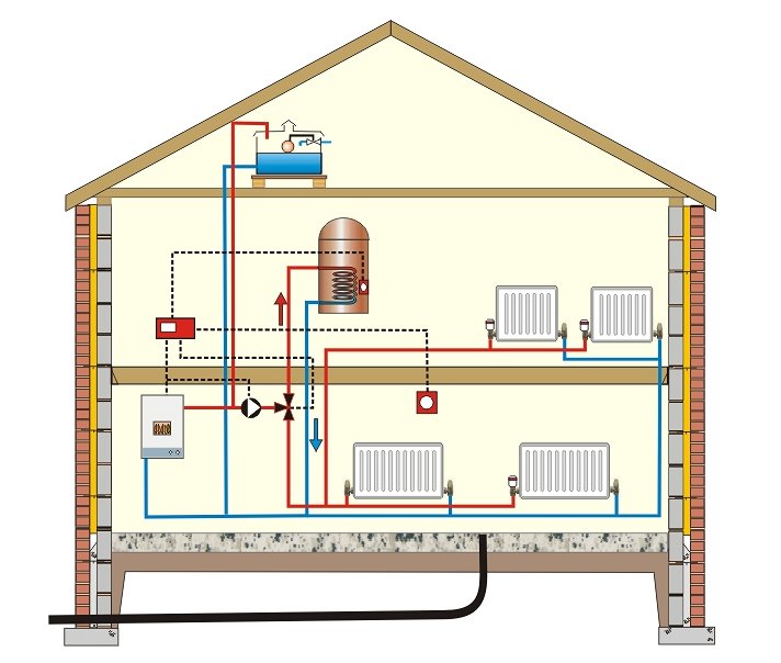
In old buildings it is common with gravity storage tanks on the top floor of the building. More commonly used in new systems are pressurized tanks and supply pumps.
Domestic Water Supply with Gravity Tank

This paper will cover every aspect of the design and construction of a water supply system utilizing potential energy (gravity) for delivery. The typical layout of a gravity-fed water system (Figure 1.1) includes a water source, transmission main, reservoir and distribution system. Every component.
Domestic water supply system with gravity tank:
For proper operation of the system the gravity tank is located at least 30 ft or 10 m above the highest outlet or consumer. In taller buildings pressure reducing valves are required in the lowest floors before the fittings. Commercial hvac load calculation spreadsheet.
The volume of a gravity tank must be designed to compensate for limited capacity of a supply line. The tank fills up when the consumption of hot and cold water is lower than the capacity of the supply line - and the tank is emptied when the consumption is higher than the capacity of the supply line.
A drawback with the open gravity tank on the top floor is the potential danger of freezing during winter conditions. Huge tanks will also influence on the construction of the building.
Domestic Water Supply with a Pressurized Tank
Domestic water supply system with pressurized tank:
The pressurized tank is partly filled with air (or gas) behind a membrane. The air compensates for pressure variations during consumption and when supply pump starts and stops.
A pressurized tank has a limited compensating capacity for the shortage in a main supply line.
Estimating Required Buffer Tank Capacity
You are free to use the template bellow as a tool to estimate required buffer capacity in a water supply system. Log in to your Google Account to make your own copy to modify of the template. Alternatively - you can also save the Google Spreadsheet to your computer as a xls file.
Related Topics
- Water Systems - Hot and cold water service systems - design properties, capacities, sizing and more
Related Documents
- Cold Water Storage Capacity - Required cold water storage capacity - commonly used fixtures and types of buildings
- Cold Water Storage per Occupant - Cold water storage for occupants in common types of buildings as factories, hospitals, houses and more
- Cross-Contamination Control - It is fundamental to keep the potable water in the water supply systems uncontaminated
- Domestic Hot Water Service Systems - Design Procedure - Design procedure for domestic hot water service systems
- Domestic Water Supply - Lime Deposits - Lime deposited vs. temperature and water consumption
- Hot and Cold Water Pipe Sizing - Recommended dimensions of hot and cold water pipes
- Hot Water Circulation Return Pipe - Hot water can be circulated through a return pipe if it's instantly required at the fixtures
- Hot Water Supply - Fixture Consumption - Design hot water consumption of fixtures - basins, showers, sinks and baths
- Legionella - Legionella pneumophila - bacterium that thrives in water supply systems and air conditioning systems - causing the Legionnairs disease
- Online Design of Water Supply Systems - Online design tool for a water supply system
- PE Water Supply Pipes - Properties - Nominal pipe size, outside diameter, wall thickness, weight and working pressure
- Sizing Domestic Hot Water Heaters - Domestic Hot-Water sizing equations - heating capacity, recovery rate and power supply
- Water - Human Activity and Consumption - Activity and average water consumption
- Water Distribution Pipes - Materials used in water distribution pipes
- Water Service Pipe Lines - Water service pipe lines extends from the potable water source to the interior of buildings
- Water Supply Pipe Lines - Sizing - Sizing of water supply pipe lines
- Water Supply to Public Buildings - Required water supply to public buildings
- Yard Fixtures - Water Consumption - Water consumption in garden fixtures
Tag Search
- en: service water supply domestic gravity pressure tank
Free download program microsoft office 2010 flyer templates. Our ‘Step-by-step’ blog series takes a look at different practices and procedures in the transmission pipeline industry.
This week we’re outlining what happens during the pipeline design process – it’s more involved than you might think! Based on over 500 pages of standards and regulations, the design for each pipeline covers every aspect from routing, materials, pipe construction, laying the pipeline, safety and pipeline integrity.
Here’s a quick look into the world of pipeline design
Pipeline design begins with a study of the proposed route, including full environmental and engineering assessments:
Designers draft detailed schematics based on over 500 pages of standards:
The composition of the steel is a key factor to in the pipeline’s integrity. That’s why alloys may be added to the steel so it meets the precise specifications:
Pipeline Inspection
Pipelines are inspected using X-ray technology and hydrostatic testing. This technician is inspecting the pipe from the inside!
The pipeline is then coated with corrosion-resistant, powdered epoxy:
During construction, huge valves are placed along the pipelines at regular intervals so the flow can be shut off in the event of a spill:
2.4 Gravity Pipeline Design Water Supply System Map
After construction, the land is remediated. Aside from above-ground facilities at intervals along the pipe, there is almost no sign that the land has been disturbed:
Of course that’s the shortened version of the process! If you’d like to learn more, watch this video for the full story:
Stay tuned as we continue this ‘Step-by-step’ series. Next we’ll take a look at pipeline technology. In the meantime, if you’d like to learn more about pipeline design, check out this blog post: Pipelines: safe by design.
The Canadian Energy Pipeline Association represents Canada’s transmission pipeline companies who operate approximately 117,000 kilometres of pipelines in Canada. In 2014, these energy highways moved approximately 1.2 billion barrels of liquid petroleum products and 5.4 trillion cubic feet of natural gas. Our members transport 97 per cent of Canada’s daily natural gas and onshore crude oil from producing regions to markets throughout North America.
Explore CEPA
Get Connected

Engage in the online discussion
